 |
|
Success for CDF's Central Outer Tracker: by Mike Perricon One of the great mysteries of science, time is also its unsparing motivator. Time dictated the function of the new Central Outer Tracker destined for a critical role in the massive CDF detector during Run II of the Tevatron. With proton-antiproton collisions occurring in greater numbers and at a faster rate than ever before at Fermilab, the Central Outer Tracker's design needed to provide chambers that could extract more information from tracing the tracks of particles over smaller intervals of both time and distance.
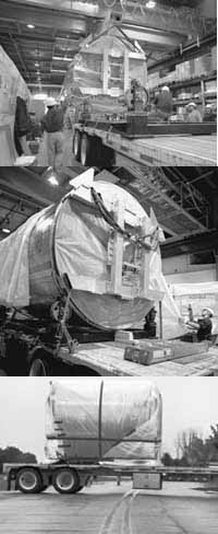
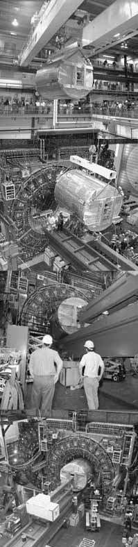
"We were very conscious that we had a very limited amount of time for a project with this level of complication," said CDF co-spokesperson Franco Bedeschi. "A lot of new engineering and technology went into the design of the chamber." When the setbacks came--primarily from endplates that were inaccurately machined, and arrived late--time drove the project managers to new levels of endurance. "The whole team that was working on this started working 24 hours a day," said CDF co-spokesperson Al Goshaw. "We needed physicists as shift supervisors from all the COT's collaborating institutions to cover the 24-hour operation. It took the dedicated efforts of many people to assemble the chamber: technicians, physicists, engineers and designers. "And one or the other of the two project leaders were just there all the time," Goshaw continued. "Any time you'd go over there, day or night, one of them was there, if not both of them." On Thursday, May 11, project leaders Aseet Mukherjee and Bob Wagner had the Central Outer Tracker taken out of their hands. Temporarily. The "can," as it's dubbed, an aluminum cylinder 10 feet in diameter and 10 feet in length, was lifted by crane off the supports where it had been assembled in Industrial Center Building 4. The supports were placed on the back of a special low-riding, air-suspensioned flatbed truck. The tracker was then lowered on the supports, secured, covered, and sent off for its painstaking drive through wind and rain, across the road to the CDF Assembly Building. The journey, a quarter of a mile at best, took a half-hour--a speed of something like two hours per mile. "I'd say the truck was moving at about the rate of a slow walk," estimated Mukherjee, "but it wasn't very far and there was no rush. We were less worried about the rain than we were about the wind. If the can blew over, obviously that would be bad. If the cover blew off, that wouldn't be so bad in itself, but it could snag on something and do some damage as it came off." But neither wind nor rain delayed the Central Outer Tracker, which was lifted off the truck and successfully inserted into the CDF detector, with two millimeters of clearance. The COT sits in the center of the CDF structure, just outside the silicon detectors that provide the closest contact with the particle collisions. There, said Bedeschi, the COT represents "a key detector to make high-quality physics measurements at CDF for Run II."
Internal Competition
The Central Outer Tracker grew from an internal competition within the CDF collaboration, complete with several different proposals examined by internal review committees, during what Goshaw described as "a very stressful time." Initially, another design was chosen; but when that design appeared as if it couldn't be completed in time, the strategy switched to adapting the original CTC and using it in Run II until the original choice was completed. But that would have meant replacing all the original electronics in the CTC to meet the new Run II requirements--with a temporary detector. It would be costly, and time was moving on.
"Mainly, we just wanted to have something we could load very quickly, because it was clear the schedule would be very tight," Mukherjee recalled. "The question was how get a large number wires installed in a short period of timeóand the idea was to overlap most of the wire work before the ëcan' was actually completed."
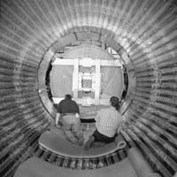
The solution, modular drift cells, were made up of pre-made wire planes and field (or cathode) planes. The wire planes consisted of 29 wires each, 12 recording the flight of the particles, and the rest shaping the drift trajectories. The field plane is made of very thin Mylar (a strong polyester film widely used in insulation, and in capacitors as the dielectric material) with a vaporized gold coating. The wire planes and field planes are attached to precision-machined aluminum end plates that bear 60 metric tons (100,000 pounds) of total tension. The wire planes were made at Fermilab's Lab 6 by Karen Kephart's group in Technical Centers and tested at the University of Illinois. The field planes were made at Harvard University and Lawrence Berkeley National Laboratory.
The wire planes and field planes were positioned in slots machined into the end plates. The slots were made quite narrow, to maximize the plate strength, and to minimize the shape-altering effects of the tension. But there were delays and inaccuracies in the machining, and some of the slots' positions did not fall within the specified tolerance.
The solution: matching individual wire planes with individual slots with the aid of a computer.
Added Wagner: "Each slot was measured on a coordinate measuring machine, so we knew the locations and features of all of them. We measured each wire plane in a similar manner, and used a computer to match them up with the best accuracy. We were able to correct a lot of problems in the machining. Of course, if everything had been perfect, we would have had a lot less to keep track of."
Not to mention needing less time. Installing the wire planes took more than four months, followed by quality control efforts to make sure the detector could stand up to 10 years or more of operation. That meant months of round-the-clock shift work: day and evening shifts with two crews of two people each, installing the planes, and an owl shift to carry out quality control checks.
Once the wires were all in and the can was sealed up, the big test was next: filling the chambers with gas and seeing if all the wires could hold 2,500 volts of electricity.
"It was astounding," said Goshaw, "because it was clear that everything was coming up to high voltage very smoothly. It was an absolutely incredible technical feat to go through all those problems and then have 30,000 wires smoothly coming up to high voltage.
"Bob and Aseet are the people who really carried out this project," Goshaw continued. "They suffered many frustrations along the way but they persisted. They knew what was right, they carried it though to this point, and now they'll be responsible for bringing the COT up to operation."
The electronics will soon be busy with the first data runóthe first proton-antiproton collisions during the commissioning run from late August to October. The COT will be critical to tuning the whole detector, and preparing to take good physics data right from the start of Run II of the Tevatron in March, 2001. Wagner, Mukherjee and all the dedicated crews who have worked on the COT are waiting to watch it turn on and light up.
"Well, we hope it doesn't exactly light up," Mukherjee said. "What we hope is to take it quietly and smoothly so nobody notices anything until they look at it when it's up and running."
Time will tell if he's right.
|
 Once the go-ahead was given in 1996, time relentlessly drove the design and assembly of the Central Outer Tracker, which surrounds the beam pipe at the very heart of CDF's operations with about five times as many information channels as the Central Tracking Chamber it replaces-- some 30,000 channels, in 2,500 separate cells, compared to 6,000 channels in the now-superseded Central Tracking Chamber.
| last modified 5/26/2000 email Fermilab |
FRLsDFx9eyfrPXgV